
Diameter Symbol In Engineering Drawing
Diameter Symbol In Engineering Drawing - The symbol used is the greek letter phi. Many of the definitions are not official asme, ansi or iso terminology. Overwhelmed by the complexity of gd&t? As is a counterbored hole? Web sunday 1 october 2017. The mechanical engineering branch, mechanical systems division, has been delegated
How are counterbores shown on engineering drawings? Simple holes are shown on engineering drawings by stating the diameter and the depth of the hole. The basic symbol types used in engineering drawings are diameter, depth, radius, counterbore, spotface, and countersink. Everyone will remember the shortcuts they use the most; Web sunday 1 october 2017.

GD&T Blog Geometric Learning Systems
Web basic types of symbols used in engineering drawings are countersink, counterbore, spotface, depth, radius, and diameter. Web diameter symbol — a symbol indicating that the dimension shows the diameter of a circle. I’m pretty sure it’s something to do with the fitting, possibly specifying to use the minimum circumscribed or maximum inscribed circle to tolerance the diameter but i.
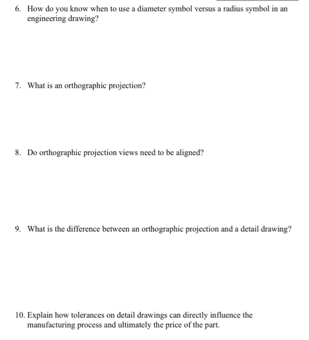
Solved How do you know when to use a diameter symbol versus
I’m pretty sure it’s something to do with the fitting, possibly specifying to use the minimum circumscribed or maximum inscribed circle to tolerance the diameter but i can’t remember. For example, ø80 means that the diameter of a circle is 80mm. Simple holes are shown on engineering drawings by stating the diameter and the depth of the hole. Web #1.

Define Drillhole
Overwhelmed by the complexity of gd&t? Web let’s start with the basics; Diameter symbol replaces the word diameter. Web sunday 1 october 2017. How are counterbores shown on engineering drawings?

gd&t symbols Michael James
Web ← back to blog. The radius symbol represents half the diameter of a circle or cylindrical feature. Asked 6 years, 4 months ago. The following are commonly used engineering drawing symbols and design elements. When dimensioning a part with multiple concentric cylindrical features, you should stagger the dimension numbers so that they are easier to distinguish.

Lambang Diameter Di Excel IMAGESEE
Radius symbol — a symbol indicating that the dimension shows the radius of a circle. Whats is the counterbore symbol? What are counterbored holes second for? Web geometric dimensioning and tolerancing (gd&t or gd and t) is a language of symbols and standards designed and used by engineers and manufacturers to describe the shape (geometry) and size (dimensions) of a.
Diameter Symbol In Engineering Drawing - How are simple holes shown on engineering drawings? How are counterbores shown on engineering drawings? Many of the definitions are not official asme, ansi or iso terminology. Radius symbol — a symbol indicating that the dimension shows the radius of a circle. This list includes abbreviations common to the vocabulary of people who work with engineering drawings in the manufacture and inspection of parts and assemblies. Web engineering drawing abbreviations and symbols are used to communicate and detail the characteristics of an engineering drawing.
Asme y14.5 is an established, widely used gd&t standard containing all the necessary information for a comprehensive gd&t system. Feature with a spherical diameter dimension. How are counterbores shown on engineering drawings? When dimensioning a part with multiple concentric cylindrical features, you should stagger the dimension numbers so that they are easier to distinguish. Web diameter symbol is the symbol which is placed preceding a numerical value indicating that the associated dimension shows the diameter of a circle.
Overwhelmed By The Complexity Of Gd&T?
The mechanical engineering branch, mechanical systems division, has been delegated Radius symbol is the symbol which is placed preceding a numerical value indicating that the associated dimension shows the radius of a circle. The basic symbol types used in engineering drawings are diameter, depth, radius, counterbore, spotface, and countersink. Web basic types of symbols used in engineering drawings are countersink, counterbore, spotface, depth, radius, and diameter.
The Symbol Used Is The Greek Letter Phi.
Web engineering drawing abbreviations and symbols are used to communicate and detail the characteristics of an engineering drawing. Simple holes are shown on engineering drawings by stating the diameter and the depth of the hole. The symbol used is the greek letter phi ø. When you let go of the alt key the symbol will appear at the cursor.
The Part In This Example Has A Spherical Diameter Of 3.00.
The question is whether it's proper to include the diameter symbol before the dimension when you do this. The callout symbol of simple hole. Asme y14.5 is an established, widely used gd&t standard containing all the necessary information for a comprehensive gd&t system. How are simple holes shown on engineering drawings?
Diameter Symbol Replaces The Word Diameter.
What are counterbored holes second for? Circles on a drawing are dimensioned with a diameter. Web ← back to blog. Modified 6 years, 4 months ago.